Electromagnetism – Antenna Radiation Patterns | How To Read Antenna Radiation Patterns
Table of Interests
Today, you and I will quickly take a look at the topic “Electromagnetism – Antenna Radiation Patterns | How To Read Antenna Radiation Patterns”.
This has become necessary as we have sen overtime that several individuals have been searching for topics related to the above topic Electromagnetism – Antenna Radiation Patterns | How To Read Antenna Radiation Patterns.

However, if you are among those that have been searching for answers to [how to draw radiation pattern of antenna, types of radiation pattern, types of antenna and their radiation pattern, antenna radiation pattern pdf, radiation pattern of dipole antenna, radiation pattern of antenna ppt, how to read antenna radiation pattern, antenna radiation pattern measurement, Electromagnetism – Antenna Radiation Patterns | How To Read Antenna Radiation Patterns], then you can see that you are not the only one.
Nonetheless, you shall get all this information right here on this blog.
Electromagnetism – Antenna Radiation Patterns | How To Read Antenna Radiation Patterns
Antennas
First of all, we should get into what Antennas are and how they are related with all that we talked about in Electromagnetic waves and Electromagnetism in general.
Antennas are a way of transmitting and receiving information through changes in the electromagnetic fields that surround them. Being based on Electromagnetism and EM waves, Antennas follow the principles of Wave Superposition, Wave Reflection, Wave Inversion, Standing waves and more.
The most important might be the Standing Wave Ratio (SWR) which shows us the ratio of transmitted to reflected energy. We of course want to keep that ratio as close to 1:1 as possible.
Transmitting Information
There are two types of information transfer, which are the FM (Frequency Modulation) and AM (Amplitude Modulation), that you are all familiar with, cause they are used in radio.
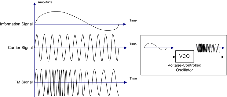
Frequency Modulation (FM)
In this type of transfer, the information is being transmitted by modifying the frequency of a carrier wave, as shown below:
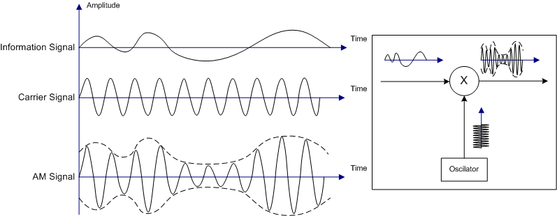
Amplitude Modulation (AM)
In this type, we keep the frequency constant and transmit the information by modifying the amplitude of the carrier wave, as shown below:
The (Simple) Dipole Antenna
The simplest structure of an Antenna is based on dipoles, which are two identical elements. That’s why such a simple Antenna is called a Dipole Antenna. The shortest dipole antennas operate at one-half wavelength (λ/2) and establish standing waves along their length.
Here’s a beautiful gif image that shows you how they operate when connected to an alternating current (AC) voltage supply:
The changing electric and magnetic field’s that are being produced at the antenna wire, create radio waves that propate outwards, following a specific radiation pattern that we will cover in-depth in a bit.
So, what exactly is happening inside of an Antenna Wire?
As a sine-wave generator is attached to the wire it creates a time-varying voltage (potential difference) along the length of the wire.
As a result of this applied potential difference that is constantly changing amplitude (or voltage magnitude) and polarity (‘+’ and ‘-‘ switch places), charges start moving inside of the wire, constantly speeding up, slowing down and changing direction of travel along the wire.
As the charges move in one direction they create electric and magnetic fields that grow as the voltage increases.
The magnetic field is of course caused by the changing electric field, as changing electric fields are one of the ways with which we can produce magnetic fields.
These fields are constantly changing with time and propagating outwards at the speed of light (speed of a EM wave in a vacuum that we can approximately consider as the speed in air also).
After reaching the maximum voltage amplitude of the AC generator, the voltage starts decreasing again, therefore also decreases the magnitude of the magnetic and electric fields.
When finally reaching “zero” magnitude the polarity reverses and starts increasing again, causing the charges to slow down, change direction and speed up again.
This change in polarity also affects the polarity of the electric and magnetic field. This procedure continues on indefinitely (As long as we supply AC voltage).
To understand this ever better, I suggest you to run the following simulation at PhET Colorado that shows you the changing electric fields generated by an electric charge:
https://phet.colorado.edu/sims/radiating-charge/radiating-charge_en.html
For the purposes of this article you should change the following Settings:
- Manual -> Sinusoidal
- Amplitude and Frequency (that show up when changing into Sinusoidal)
Of course you can also stay in “Manual”-Mode and just play with it! 😛
Regions
One last thing that we should note is that the outside region of an Antenna is splitted into regions:
- The region close to the antenna, where d << λ (the distance is far less than a wavelength) where the near field is dominated by magnetic fields
- The transition zone for 1-2 wavelengths (1-2 λ)
- The far-field region (d > 2λ), where the electric field becomes dominant as it is more regularly patterned
Most antennas operate in the far-field region, transmitting information over long distances through changing electric fields.
Near-field antennas utilize strong magnetic fields in a region near an antenna and are used in near-field communication, where the communication is limited to a few wavelengths.
Note that short doesn’t mean that we have to use near-field communication.
Radio transmitters such as nRF24 and Bluetooth devices that have a limited range, still operate based on far-field communication. RFID and NFC tags that have shorter ranges use near-field communication.
Reflectors
To redirect the energy that would radiate behind an antenna, we use reflectors that propagate the incoming radiation in the forward direction. Such reflectors receive and capture energy from a large area and reflect this energy toward a receiving element.
When transmitting, the electromagnetic radiation is therefore being concentrated along a central axis.
For example, UHF television antennas have four such reflectors that collect and reflect the radio waves that would otherwise pass by, having reflecting elements on the far side of a folded-dipole receiving element.
Directors
Similar to reflecting elements, Directors are added to antennas to change the shape of the radiation pattern.
The length and spacing of them is such that they absorb the energy and remit it in-phase with the incoming waves, directly to the receiving element or directly from the transmitting element.
That way we have a constructive interference (add-up of waves) only in the forward direction, whilst the waves form the side are absorbed and reemitted out-of-phase, leading to a destructive interference.
Antenna Properties
Being a type of electronic circuit, antennas of course have electromagnetic properties (some of which we already know from previous articles), which are:
(Electric) Permittivity
The permittivity of a material, gives us a measure oh how readily charges can align themselves (polarization) in the presence of an electric field.
Higher permittivity indicates a stronger resistance when forming an electric field, which means a slower propagation of disturbance through the medium.
A high-permittivity material that surrounds a low-permittivity material will not affect the frequency of oscillation, but the high-permittivity material reduces the speed of the wave’s propagation.
Knowing that the velocity, frequency and wavelength are binded by:

and knowing that the frequency doesn’t change, we understand that what happens is a reduction of wavelength. When reducing the wavelength the penetration through a material of course becomes more difficult.
When embedding an antenna into a high-permittivity material, the size of the antenna can therefore be reduced in accordance with the decreased wavelength of the EM waves, when interacting with this material.
Something worth noting is that waves can be inverted (180-degree phase shift) when travelling from a low-permittivity material to a high-permittivity material (or from a high-propagation-speed to a low-propagation-speed material).
(Magnetic) Permeability
Another factor that we should keep in mind, is the magnetic permeability of the antenna.
The signals emitted from antennas are electromagnetic radiation, where both electric and magnetic fields are involved.
Both permittivity and permeability affect the propagation of electromagnetic waves, resulting into a slower wave speed and decreased wavelength.
You might remember the following equation for the speed-of-light:

where:
- c is the speed of light
- ε0 the permittivity of free space
- μ0 the permeability of free space
You can see that these two factors influence the speed of light, the same way as they affect the electromagnetic propagation through a material that has a specific of permittivity and permeability .
Directivity, Efficiency and Gain
Let’s consider a isotropic antenna, which is a theoretical point source that spreads electromagnetic energy equally in all directions.
For this antenna with surface area = 4πr^2, we can define the total radiated power and power density the same way as we did in EM waves using integrals. [I will leave out the math]
As actual antennas don’t spread equally, we define a so called peak directivity, which is the ratio of the power densitity of a physical antenna in it’s most concentrated direciton to that of a theoretical isostropic emitter of the same total power tranmission level.
As a mathematical equation this looks as following:
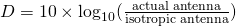
The directivity is expressed as an ordinary number that represents the ratio or in dB, where larger numbers represent more focused beams. An equally radiating antenna would have a directivity of 0 (0 dB).
Depending on the application we have:
- Low-directivity antennas that transmit and receive information from all directions more or less equally./ These are used in mobile applications, where the direction of the transmitter and receiver can change
- High-direcvitiy antennas that are able to transmit and receive information over greater distances, but have to be aimed towards another antenna. These are used in satellite television.
Another important thing that we have to take into account is the efficiency of an antenna.
The efficiency shows us the actual losses of a particular antenna design due to manufacturing fauls, surface coating losses, imperfections, impedance mismatch, or any other factor.
Combining the effect of directivity and efficiency, we talk about gain, which is:

While directivity is always greater than or equal to 1 (0 dB), antenna gain can be less than 1 (0 dB).
Radiation Patterns
Different antennas produce different radiation patterns.
The complexity of those patterns of course depends on the antenna’s design and construction.
A simple way of understanding all the things that we talked about until now (function of an antenna, directivity, etc.) is by taking a look at the radiation pattern.
A Radiation pattern is diagrammatically representation of the distribution of radiated energy into space, as a function of direction.
Graphically, we plot the electric and magnetic fields as a function of the angular and radial distance from the antenna, which means that we represent them in spherical coordinates as E (θ, Ø) and H(θ, Ø).
The radiation pattern of dipole antenna can be for example:
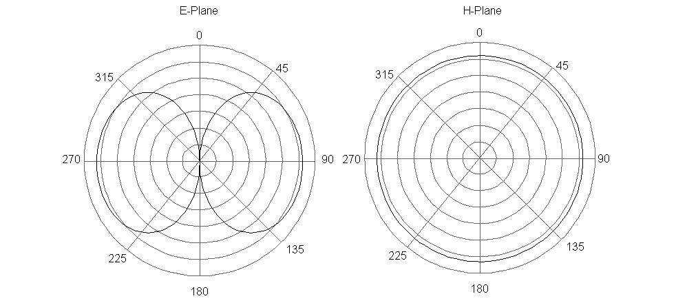
There are basically two ways of plotting radiation patterns:
- Field patterns -> Plotted as a function of electric and magnetic fields in logarithmic scale
- Power patterns -> Plotted as a function of the square of the magnitudes of the electric and magnetic fields in logarithmic or commonly dB scale
We also separate them based on the Dimensions as:
- 3D Radiation patterns -> represented in spherical (r, θ, Φ) or cartesian coordinates (x, y, z)
- 2D Radiation patterns -> that we get “dividing” the 3D into the horizontal (horizontal pattern) and vertical planes (vertical pattern)
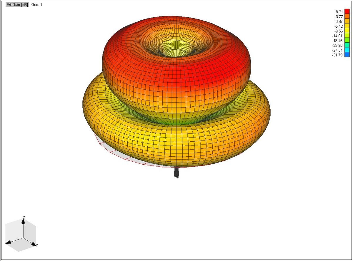
The 3D power radiation pattern of a specific Antenna looks as following:
The previous two planes for E (electric field) and H (magnetic field) where already horizontal and vertical 2D radiation patterns, cause, as you might remember from EM waves, the electric and magnetic waves are perpendicular to each other.
Lobe Formation
In radiation pattern representations we often come across different shapes, which indicate the major and minor radiation area.
These so called Lobes show the radiation efficiency in different areas.
Let’s consider the following radiation pattern of a dipole antenna:
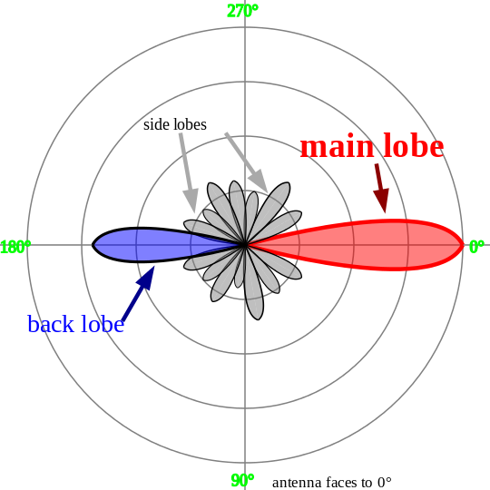
This radiation pattern is build up of:
- a main lobe or major lobe, which is the major part of the radiated field that covers the largest area. At this area the maximum radiated energy is being emitted. The direction of this exact lobe indicates the directivity of the antenna.
- the side or minor lobes, which are the areas where the power is being wasted
- the back lobe, which is a “special” minor lobe as it is exactly in the opposite direction of the main lobe. A considerable amount of energy is wasted here.
Common Types of Radiation patterns
Let’s now get into some of the most common types of radiation patterns…
Omni-directional (or non-directional) pattern
Omnidirectional antennas, which are commonly reffered as “omnis” have usually a doughnut shape in three-dimensiona view.
In two-dimensional view they form a figure-of-eight pattern. Omnidirectional antennas have usually more gain than a dipole, but a dipole is still an omni by just being aspecial case.
The 2D radiation pattern of the special case dipole is:
We already analyzed dipole antenna’s as the “simple” antenna.
Another form of Omni Antennas are the so called Collinear Omni Antennas, which have higher gain, multiple omnidirectional structures that can be arranged in vertical forming a so called collinear array.
Of course higher gain doesn’t mean higher power, as the same amount of power is just radiated in a more focused way. An example of such a pattern can be found in [Image 6], which by chance is a Omni radiation pattern.
Directional antennas
Such antennas are used for coverage as well as point-to-point linkage.
They can be of a variety of shapes that includes patch antennas, dishes, horns or a whole host.
What they all have in common is radiating energy out in a particular direction.
Let’s get into some of those more in-depth..
Patch antennas
This is the simplest form of directional antenna.
It’s a single rectangular or circular conductive plate that is spaced above a ground plane. They have a low profile and ease of fabrication, which makes them pretty common.
The radiation pattern of a single patch is characterized by one single main lobe of moderate beam width. Manipulating the beam width we can produce antennas with higher or lower gain.
The so called azimuth and elevation plane patterns are derived by simply slicing through the 3D radiation pattern of the Patch Radiation pattern.
Patch Array Antennas
Arranging multiple patch array antennas we end up with the so called patch array antenna.
All these patch antennas are driven by the same source and consist of patches arranged in orderly rows and columns (rectangular array). Such an arrangement gives us higher gain and narrower beam width.
Yagi Antennas
A Yagi antenna is formed by driving a simple antenna and shaping the beam using a well-chosen series of non-driven elements whose length and spacing are tightly controlled.
Such a antenna radiates it’s energy out in one main direction and are often enclosed in a tube.
Here’s a picture of such a Yagi antenna:
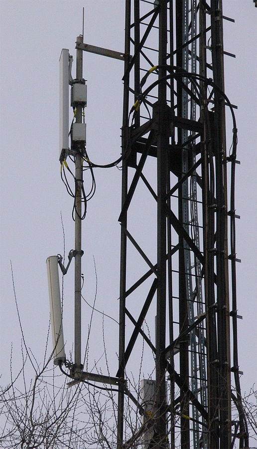
Sector antennas
A sector antenna or sector panel is a specialized antenna that is frequently encountered in outdoor systems where wide coverage areas are desired. Often they are built from an array of dipoles placed in from of a shaped reflector.
The size and shape of the reflector determine the performance.
This is a sector antenna:
Why are they useful?
We already said that these kind of representation of the antenna’s radiation, gives us information about the function, directivity, gain etc. of a specific antenna. A radiation pattern is similar to a road map, telling us where radiation is concentrated.
We can determine the most important antenna characteristics. directly referring to that plot. What most antenna users are interested in is the directivity and beamwidth of the antenna.
Another pretty popular antenna specification is the “front-to-back” (F/B) ration, which is defined as the difference in dB between the maximum gain or fron of the antenna (usually 0) and the point exactly 180 degrees behind the front.
From the radiation pattern we can see where power is being radiated or received, telling us how much degradation we can expect when the antenna is not aimed correctly.
This can be useful in cases where we might want to communicate with more than one station at once.
The antenna plotting (radiation pattern) can assist in the proper aiming and optimum performance on all the desired signals/communications.
Also, don’t forget that the weather may also affect the antenna’s performance, meaning that the type of antenna mounting also plays a big role. Interfering signals might be picked up by the antenna, meaning that we can also determine the actual level of interference of such signals usind the radiation pattern, placing them in null or low side lobe positions.
To sum up we can say that:
Antenna radiation plots are an important tool for antenna designers and users alike. Knowing how to use them will go a long way to compare different antennas and alternative solutions. When the user has this type of data at his/her disposal, the antenna performance can be better optimized to the applications.
That’s the much we can take on the topic “Electromagnetism – Antenna Radiation Patterns | How To Read Antenna Radiation Patterns”.
Thanks For Reading
Leave a Reply